Hardware
This page serves as a manual for building the same drone that we used for our project. It contains a list of all the necessary parts, a soldering plan, and instructions for modifying the frame.
Components
Drone components
Following are the components which are necessary to build and FPV drone:
Flight- & Electronic Speed Controller | SpeedyBee F405 Mini BLS 35A 20x20 Stack:
The flight- and electronic speed controller stack is the brain and muscles of the drone. All electrical components are soldered to the stack.
Motor | XING-E Pro 2207 FPV Motor
With the propellers attached to the motors and the power supplied by the ESC the motors generate thrust to lift the drone up from the ground
Propellers | ETHIX S4 LEMON LIME PROPS:
The propellers are mounted on the motors to lift the drone. In this case 5" tri-wing propellers are used, this defines the size of the drone overall
The page Rotors provide a detailed description of how to mount the propellers.
Frame | FlyFishRC Volador II VX5:
The frame is the housing for mounting all parts of the drone, giving it stability.
Video Transmitter | SpeedyBee TX800 VTX:
The video transmitter sends the video signal from the FPV camera via a specific channel.
As this is an analogue transmitter, the FPV goggles must be compatible. Companies like DJI offer its own digital transmission standard, which provides better video quality, but is much more expensive.
FPV-Camera | CADDXFPV Ratel Pro Analog:
The FPV camera captures video and sends it to the pilot, enabling them to fly the drone from a first-person view.
A controller for changing camera modes is shipped with the camera, but it is not necessary to use it because the FC can also control it.
ELRS-Receiver | SpeedyBee Nano 2.4G 2.4G-TCXO 915M ExpressLRS ELRS Receiver
This receiver enables the flight controller to receive inputs from the remote control to control the drone.
For communication, the open source protocol ExpressLRS is used.
GPS Module: HGLRC M100.5883 GPS:
The GPS module tracks the drone's location. This is not necessary for the AI features to work, but it is helpful for features such as locating the drone if it gets lost.
Remote | Radiomaster Zorro:
The remote must have a software version installed which supports the protocol of the used receiver on the drone. In our case it has to support ExpressLRS.
We flashed with Buddy EdgeTx the new software on the remote via USB-Connection. In the case of the Zorro the top USB port must be used.
Battery Pack | Tattu 650mAh 4S1P 75C 14,8V Lipo-Battery pack
The battery pack is the drone's power source.
We used 4S battery packs, meaning they have four cells.
The capacity determines how long the drone can fly for, but it also adds additional weight.
FPV-Goggles Skyzone CobraS:
The goggles can be used to fly the drone in first-person view mode, with the image transmitted by the drone.
The image quality received can be compared to that of an older camcorder.
Charger SKYRC S100 neo AC/DC Smart Balance Charger:
The SkyRC S100 can charge drone battery packs and also read their status.
A special charger is necessary for LiPo batteries to ensure the cells don't get damaged.
Components for AI Application
Additional components are necessary to add AI capabilities to the drone:
Single Board Computer | Raspberry Pi Zero 2 W:
The Raspberry Pi is the brain for the AI application
Communication with the FC via UART connection using the MSP protocol
Control of the electro magnet for the package transportation
Camera | Joy-it 8MP 120° Camera:
Camera for computer vision of the Raspberry Pi
TPU Accelerator Google Coral TPU USB Accelerator:
To enhance the Raspberry Pi's processing power for AI applications, the Google Coral is used. Connected via USB, it gives the Pi a performance boost, making it feasible for real-time operations.
Components for Package delivering
To be able to deliver small packages with the drone, additional components are necessary:
Relay | Tongling 5VDC JQC-3FF-S-Z:
The relay is needed to toggle the electro magnet. It is connected to the Raspberry Pi, which then can power the electro magnet on and off via the relay.
Electro Magnet:
Used to pick up small light packages for transportation via drone
Soldering
The two main components of a drone are the flight controller (FC) and the electronic speed controller (ESC). Stack. Initially, the SpeedyBee F405 AIO 40A Bluejay was used, which combines the functions of the FC and ESC in one unit. However, a shortage damaged the FC during soldering of the drone. A shortage damaged the FC while soldering the drone.
With the SpeedyBee F405 Mini BLS stack, soldering can be completed in two steps. First, solder the motors and the battery connector to the ESC. Then, solder the rest to the FC. Once soldering is complete, connect the FC and ESC using the provided cable.
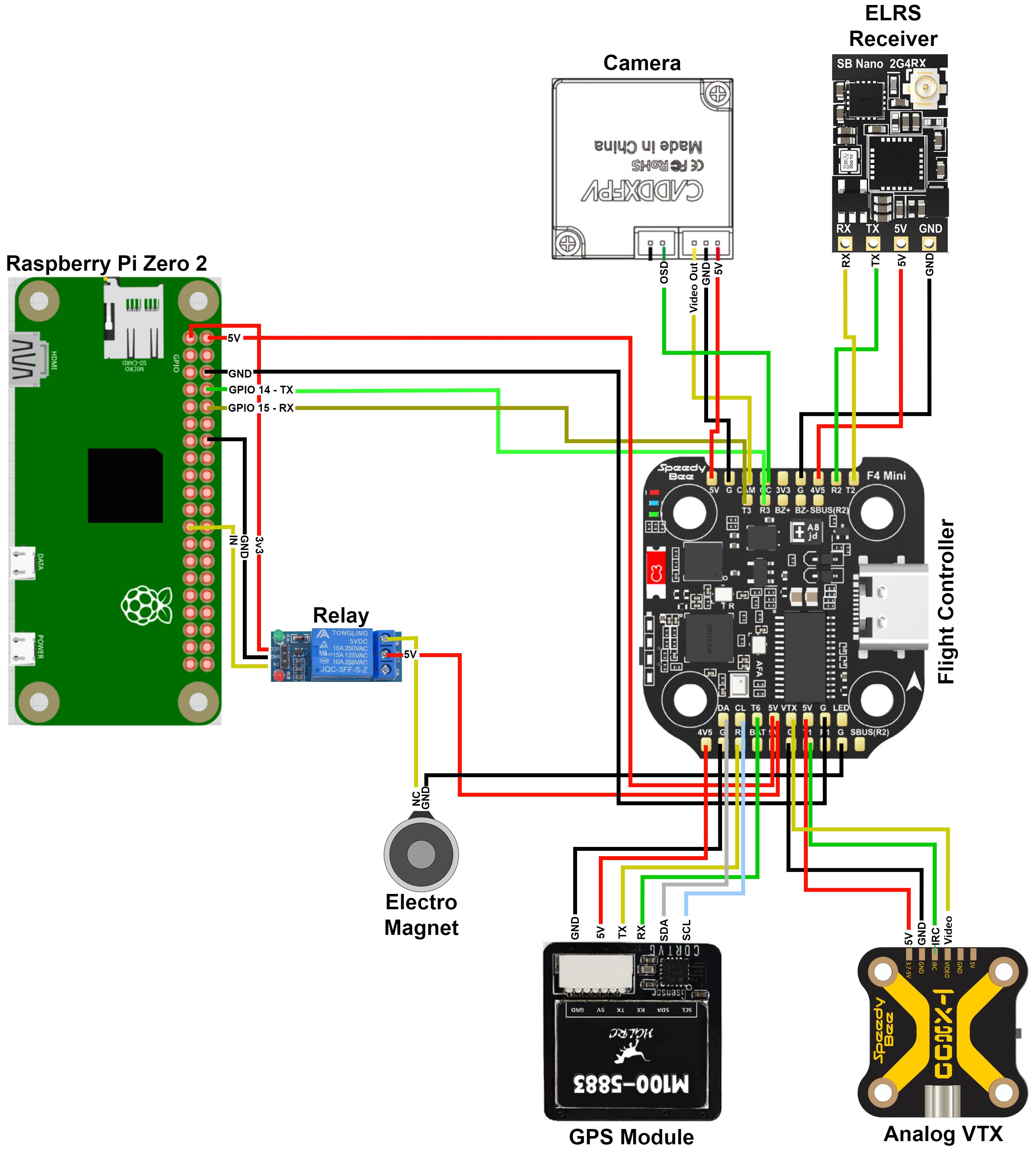
Soldering plan Flight Controller
The camera, ELRS receiver, GPS module, video transmitter, and Raspberry Pi are soldered to the flight controller. When soldering some components, it is important to note that the cables for UART communications (RX/TX) must be crossed. For example, the RX of the ELRS receiver must be connected to the corresponding TX pin on the FC, and the TX pin of the receiver must be connected to the RX pin on the FC.

Soldering plan Electronic Speed Controller
To solder the motors, solder the three cables to the ESC. It is important to solder the motors in the order in which they are placed on the frame.
To prevent damage to the ESC and FC from voltage spikes, a capacitor is soldered to the power connection. It is recommended to add insulation to the capacitor connectors.
Frame Modification
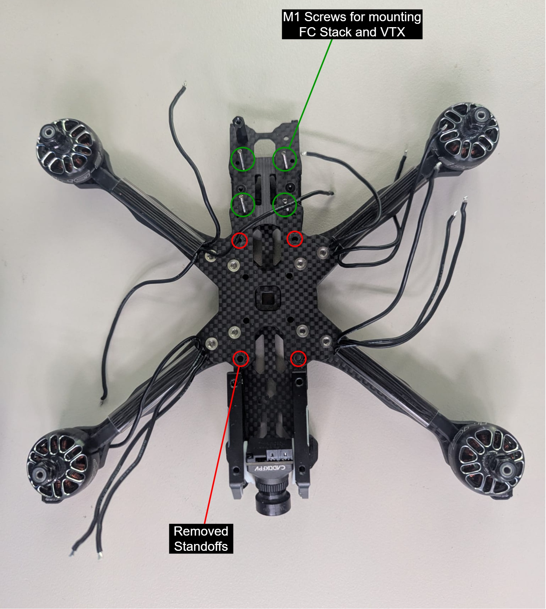
The off-the-shelf drone frame is designed for building a simple FPV drone without any additional features. We therefore had to modify it to accommodate the Raspberry Pi and Coral. There are two ways to achieve this. Either all the AI components can be strapped to the top of the drone, which requires less modification, or they can be placed inside the frame. We decided to place them inside the frame for better protection and a more compact drone.
To achieve this, as can be seen in the picture, the FC stack and the VTX are stacked on top of each other at the rear of the frame. This is a tight fit because the FC stack is usually placed in the center of the frame. Instead, four of the standoffs that would usually support the top of the frame are removed. This creates enough space in the center of the frame to place the Raspberry Pi and Coral on top of each other. The frame remains stable, and we experienced no issues with its stability. 